Granduc Mine
The Mine in Operation - Continued
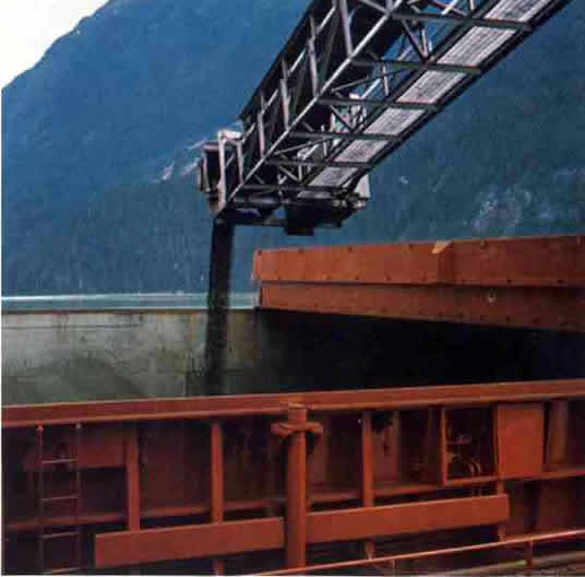
Photo - Ship Loader
POWER PLANT
Layout of the facilities were taken into account future installation of automated dumping and stockpiling system whereby the trucks will be dumped at the fuel load-out station and concentrate conveyed to the storage building for stockpiling by overhead traveling tripper conveyor .
The wharf consisted of six similar dolphins and was designed to withstand a 50,000-ton deadweight ship approaching at 0.33;:ft.( sec. normal to the berth face. Minimum depth of water at the berth face was 40 feet at low tide which required the dredging of some 60,000 cu. yd. of material at the inshore end of the berth.
The ship loader-support structure was in the form of an elongated T -shape some 50 ft. wide across the head with a 180-ft. tail, oriented at right angles and central to the berth face; the structure consists of 110 piles. A seventh dolphin was located on the ship loader centre line but was completely independent of the support structure.
Essentially the approach trestle was a connecting service bridge, 580-ft. long, carrying the concentrate conveyor and 14-in. fuel unloading line on pilings placed at 20-ft. centres.
Power Plant Ships would be berthed without the assistance of tugs. Four mooring buoys were provided. Granduc was an isolated mine, and that fact alone dictated the need for complete power-plant facilities on site.
It can be said without reservation that this was one of the most up-to-date and efficient power-generating facilities. Capacity of the plant is 30 MW.
Two oil-fired boilers rated at 260,000 Ib. per hour generate superheated steam at 600 psig and 725° to evaporation condensing turbines driving 15 MW generators. In addition there were five auxiliary Caterpillar diesel generators located in the diesel room on the ground floor of the plant. Two of these machines were rated at 400 k.w. and three at 500 k.w., al12300 volts, 3 phase, 1200 r.p.m. When operated in parallel the turbo-generators had a generating capacity in excess of the anticipated peak load.
In the event of one of the turbo- generators being down for any reason, the other units were capable of supplying and maintaining continuity of essential services and most of the load requirement. In addition, each of the boilers was capable of supplying enough steam to satisfy the power demand for the entire plant.
Each of the two generators energizes a 13.8 kv bus section which carried all the feeder loads and which was also tied into the 2.3 kv diesel bus through two transformers.
Generally speaking, the diesel units were used to provide auxiliary power for initial start-up of the first turbo-generator, emergency power or supplementary power, should one turbo-generator be shut down.
Applications of the power were made at 4160 volts and 600 volts throughout the surface facilities. Underground operations were supplied at 22.9 k. v. by twin 25 kv feeders running through the tunnel.
During normal operations the two turbo generators were operating in parallel, supplying equal or apportioned loads to all feeder circuits. The diesel units were not in use under such operating conditions.
The plant was modem in every respect and a complete system of controls, alarms, and other built-in relays, meters, and switches assured instant knowledge of water levels, frequencies, output voltages, and any kind of extraordinary electrical or mechanical malfunction.
In addition to this power-generating equipment, there were also a package boiler for emergency heating of the plant; a 75 ph. electric fire pump and an 82 hp. gasoline-powered fire pump were located in the fire-pump house on the ground floor. Each pump was rated at 80 p.s.i. differential. A system of hose stations and automatic sprinkler installations were arranged through the concentrator and power plant buildings.
The two buildings were connected by an 8-ft.-dia. by 372-ft.-Iong underground service-tunnel which carried I I pipe runs plus cable and conduits.
Fuel oil for the power plant was unloaded on the return trip from Stewart and pumped to two 20,000-gal. storage tanks, each 60 ft. in diameter and 40 ft. high. Fuel oil for the concentrate dryer was carried in a separate tank located on the 2540-ft. level in the concentrator building.
OPERATION-CONTINUED