Granduc Mine

The Mine in Operation - Continued
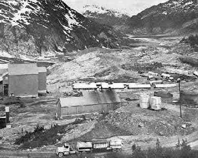
Photo - Granduc surface showing the outside water storage
SEWAGE AND WASTE SYSTEMS
Even at the mine site Granduc was, in provision had been made for the treat effect, a fairly large community. Amplement of sewage and wastes. A sanitary sewage system connected eight washrooms in the concentrator and one in the powerhouse and discharges from the west side of the building to a sewage-treatment plant below the concentrator. Clear effluent was discharged into the canyon below.
Treatment plant was an Aero-flow package unit sized for 500 men and can handle 10,000 gallons of domestic sew- age daily.
WATER SUPPLY
Truck and trailers loaded with concentrate leave mill southbound for Stewart. Power-house is immediately above truck and corner of mill building is in left centre.One of the welcome developments at Granduc was the presence of a substantial flow of ground water, more than adequate for all present and future requirements of the entire operation.
Water requirement for the concentrator and power-plant complex was initially set at 5,000 gallons per minute. Although some consideration was given to using mine water as a source of supply, the early demands of the power plant, which was in operation well in advance of mine development, required an alternative source.
Drill tests in the valley, two miles from the concentrator, disclosed three water-bearing areas capable of supplying 10,000 g.p.m. on a continuous basis. The well-drilling activities were carried out in what was the site of Tide Lake which is now vanished. As a result of the initial encouragement, five wells were drilled and a gathering system in- stalled in 1968. Storage capacity of the aquifer complex had been set at 4 billion gallons of which approximately half would be available to the well field. Under drought conditions of no re- charge, hardly conceivable considering the location, a 5,000 g.p.m. with-drawl was possible for some 250 days.,
The well pumps were Worthington deep-well turbine pumps rated at 800 to 1200 g.p.m. A transfer pumphouse was mounted over a 44,000-gallon concrete sump located centrally to the wells. This pumphouse contained four booster pumps also manufactured by Worthington. The water was pumped to a 400,000-gallon water-storage tank, 42Y2 ft. in dia. by 40 ft. high, above the power house.
Water was distributed through various systems for cooling water, the concentrator processes, the power-plant requirements, drinking and washing, and fire protection. It is worthy of note that the water for the boilers required minimal if any treatment and for drinking purposes the water had been declared virtually pure and meets all health regulations.
Industrial water runoff, shower drainage, floor waste in the process areas, etc. were collected in sumps and pumped back into the circuit where two trunk lines discharge into the tailings system.
NEXT THE TOWNSITE